
Construction Scheme for High Slope Protection with Prestressed Anchors
Release Time:
2023-06-15
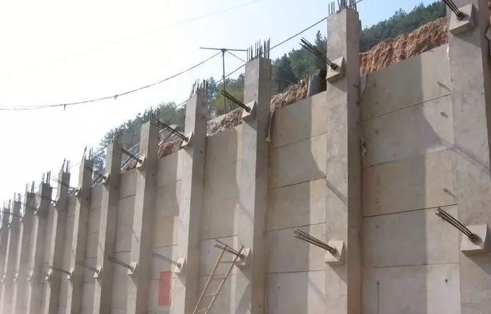
For mountainous highway construction, earthwork excavation is substantial, with high roadcut slopes and generally poor geological conditions. Prestressed anchor cable beams are typically used to ensure the stability of high slopes. Construction of prestressed anchor cable beams is a specialized operation with complex geological conditions, hidden key engineering aspects, and significant technical challenges. A specialized construction team with professional training and extensive experience should be assigned to the project. The main construction procedures are as follows:
1. Anchor Hole Surveying and Layout: Slope construction involves simultaneous excavation and reinforcement; each level is excavated and protected before proceeding to the next. According to the project elevation drawings for each work point, the anchor hole positions are accurately surveyed and laid out on the slope surface, with positional errors not exceeding ±50mm. If the existing cut slope surface is uneven or presents special difficulties, the design and supervision units must approve any adjustments. Positioning accuracy may be relaxed or anchor hole positioning adjusted, provided slope stability and structural safety are ensured.
2. Drilling Equipment: The selection of drilling equipment depends on the type of anchoring stratum, anchor hole diameter, anchor hole depth, and site conditions. Percussion drilling is used in rock strata; in fractured or loose, water-saturated strata prone to collapse or drill bit jamming, casing drilling techniques are employed.
3. Drill Rig Positioning: For anchor hole drilling, scaffolding with adequate load-bearing capacity and stability is erected. Based on the slope surface hole position survey, the drill rig is accurately installed and secured. Rig positioning is carefully adjusted to ensure that the longitudinal and transverse errors of the anchor hole drilling position do not exceed ±50mm, the elevation error does not exceed ±100mm, and the drill hole inclination and direction meet the design requirements. The allowable error for inclination is ±1.0°, and for azimuth ±2.0°.
4. Drilling Method: Dry drilling is required; water drilling is prohibited to prevent deterioration of the slope rock mass engineering geological conditions and to ensure the bonding performance of the hole wall. Drilling speed is strictly controlled according to the drill rig performance and anchoring stratum to prevent drill hole distortion and diameter changes, which could lead to anchoring difficulties or other accidents.
5. Drilling Process: During drilling, detailed on-site records are kept for each hole, including stratum changes, drilling status (drilling pressure, drilling speed), groundwater, and any special circumstances. If any adverse drilling phenomena such as hole collapse or contraction occur, drilling must be stopped immediately, and grouting must be carried out (grouting pressure 0.1~0.2MPa). Drilling resumes after the cement mortar has initially set.
6. Hole Diameter and Depth: The anchor hole diameter and depth must not be less than the design values. To ensure the anchor hole diameter, the actual drill bit diameter must not be less than the design hole diameter. To ensure the anchor hole depth, the actual drilling depth must exceed the design depth by 0.2m or more.
7. Anchor Hole Cleaning: After reaching the design depth, drilling should not be stopped immediately; hold for 1-2 minutes to prevent the bottom of the hole from being destroyed and failing to reach the design diameter. The anchor hole walls must be free of debris and water adhesion and must be thoroughly cleaned. After drilling, high-pressure air (air pressure 0.2~0.4MPa) is used to remove all rock powder and water from the hole to prevent a reduction in the bonding strength between the cement mortar and the hole wall rock and soil. High-pressure water flushing is prohibited except for anchoring in relatively hard and intact rock masses. If pressurized water flows out of the anchor hole, anchoring and grouting should only proceed after the water pressure and flow rate decrease. If necessary, drainage holes should be set up in appropriate surrounding locations. If the design requires the treatment of accumulated water in the anchor hole, methods such as grouting and secondary drilling are generally used.
8. Anchor Hole Inspection: After anchor hole drilling, on-site inspection and approval by the supervisor is required before proceeding to the next step. Diameter and depth checks are generally performed using the design diameter drill bit and standard drill rods under the supervision of the on-site supervisor. The drill bit should advance smoothly during the inspection process without impact or vibration. The drill rig inspection length should meet the design anchor hole depth, and the drill withdrawal should be smooth. High-pressure air blowing should not reveal significant splashing debris or water. The anchor hole position, inclination, and azimuth should also be rechecked. Once all anchor hole construction sub-items are qualified, the anchor hole drilling inspection is considered complete.
9. Anchor Cable Fabrication and Installation: The prestressed anchor cable consists of four parts: the anchor beam, the free section, the anchoring section, and the safety section. A pressure-dispersed anchor cable is used, consisting of three unit anchor cables. Each unit anchor cable consists of two unbonded steel strands anchored in a steel carrier. The steel strands are symmetrically anchored to the steel carrier using special compression springs and compression sleeves. The connection strength of a single strand must be greater than 200KN. The steel carrier must be made of No. 45 steel with a thickness of no less than 2cm. High-strength, low-relaxation, unbonded prestressed steel strands with diameters of φj15.24mm and φj12.7mm are used. Before installation, ensure that each steel strand is straight, untwisted, unbent, and evenly arranged. Remove rust and oil stains, and remove any dead bends, mechanical damage, or rust pits. Wire loops are installed every 1.0~1.5m along the anchor cable axis to ensure a protective layer thickness of no less than 20mm. Before installing the anchor cable, double-check the anchor hole number. After confirmation, blow the hole with high-pressure air and slowly insert the anchor cable into the hole. Measure the length of the steel strand exposed outside the hole with a steel ruler, calculate the length of the anchor cable inside the hole (error controlled within 50mm), and ensure the anchoring length.
10. Anchoring Grouting: Cement mortar is used for grouting, with the mix ratio determined after testing and selection. The actual grouting volume is generally greater than the theoretical grouting volume, or the grouting is considered complete when the anchor fitting vent no longer vents and thick grout overflows from the hole. If the hole is not fully grouted or settlement occurs after grouting, supplementary grouting is required until full. After grouting, the grouting pipe, grouting gun, and grouting casing are cleaned, and grouting records are kept.
11. Beam Construction: The beam is cast in place using C25 concrete. A 2cm mortar leveling layer is first laid on the foundation, followed by steel reinforcement fabrication and installation. Steel bar joints must be staggered, and the number of steel bar joints in the same section must not exceed 1/2 of the total number of steel bars. The distance between sections with welded joints must not be less than 1m. If the anchor cable interferes with the vertical beam hoops, the spacing of the hoops can be adjusted locally. Concrete pouring, especially around the anchor holes where the reinforcement is dense, requires careful vibration to ensure quality.
12. Anchor Cable Tensioning, Locking, and Grouting: The tensioning and locking process will be determined through on-site tensioning tests. Anchor cable tensioning and locking will be carried out in stages, strictly in accordance with the operating procedures. A compensation tensioning will be carried out 6-10 days after the design tensioning is completed, and then locked. After compensation tensioning, leave 5-10cm of steel wire from the anchor, cut off the rest. Mechanical cutting is required; arc cutting is strictly prohibited. Finally, fill the gaps in the anchor plate and anchor head with neat cement slurry, and then grout the anchor head with concrete of not less than 20 MPa to prevent rust and enhance aesthetics.
Disclaimer:
Unless otherwise stated, articles published on this website are reproduced from online sources, excluding those from the original channel;
The views expressed in the articles do not represent the position of this website; the authenticity is the responsibility of the author or the source.
If you have any copyright or other disputes regarding articles and images, please contact us in time, and we will delete the relevant content after verification.

Mobile QR Code
Liuzhou Jianqiao Prestressed Intelligent Equipment Co., Ltd.
Email:1370838748@qq.com
Address: No. 99, Xiaolongwen Road, Liunan District, Liuzhou City
Mobile:+86 13978051832
Mobile:+86 13877223782
Whatsapp:+86-13687716583
Copyright © 2025 Copyright: Liuzhou Jianqiao Prestressed Intelligent Equipment Co., Ltd.